Tempest Manual
Before the first use, thoroughly clean the parts with a Q-tip, following the instructions in the cleaning section of the manual.
How to use
Loading the bowl
Unscrew the cap and fill the bowl by pushing it into your ground material or using the hoover / straw method. It's important to keep the threads clean and ensure good airflow, only light tamping is recommended. Screw the cap on gently until it is fully closed. Try to avoid touching the steel parts of the cap, as the oil residue from your fingers might burn onto it.
Heating with a torch
Hold the tip of the flame about 1 cm (1/3 in) away from the cap. Listen for the click and keep an eye on the visual indicator while slowly rotating the device for even heat distribution. The indicators respond based on where you heat the cap, so use the ring markings as reference points. Aim a little closer to the air slots with triple or large torches, but never heat the indicators directly.
Heating with the Wand IH
To activate the Wand, press the main button twice. Set the "temperature" to adjust the desired heating time, and allow it to run until the "Time over" message appears. A temperature of 280°C / 525°F is typically a good starting point for Zirconia balls. Please read the detailed initial setup process below.
Debowling
Use the leather case, the Reload's magnet, or the tool on the underside of its lid (Gen 2 only) to securely hold the hot cap and twist it off to open and empty the used material. You can use the leather case for storage, even if the cap is still hot. Instead of pulling, tilt the device to remove it from the magnet. Store the device in a safe place, as the cap retains significant heat for a few minutes.
Additional info
- The most effective technique is to take long, slow draws while covering the air hole for the majority of the draw.
- The click disc will change slightly during the first 10 to 30 uses.
- We recommend using a triple, dual or medium size single-flame torch.
- For a more pronounced initial flavor and increased convection, move the torch closer to the air slots and expect slightly early indicators.
- During re-heats, don’t go as far on the visual indicator as initially; stop heating about one marking earlier.
- The visual indicator may continue to move as the heat spreads and equalizes within the cap. Never heat the indicators directly.
- Try not to touch the heated parts of the cap, as the oil from your fingers will burn onto it.
- Compatible induction heaters: iSpire Wand (max 100W), Vestratto Forge
- The double o-rings next to each other on the Tip and Cooling Unit are different sizes. You can find the specific sizes on the airflow diagram below where the sizes are marked with different colours. (ID x CS mm) 7x1mm - Green, 6x1mm - Grey , 5x1mm - Black.
Setting up the Wand IH and adapter
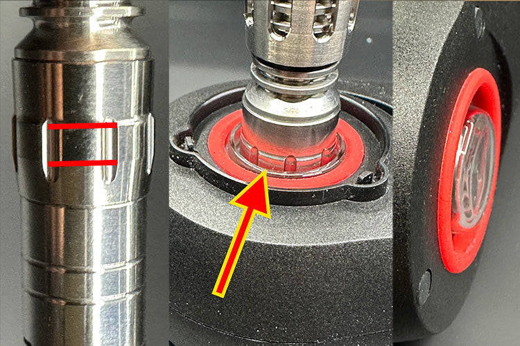
After installing the adapter following the video guide below, gently press it down with your Tempest until the area marked within the two red lines on Cap is at the top of the Wand's glass. We recommend adjusting it within the marked range on the cap in relation to the top of the glass to avoid heating too low or too high. Initially, adjust it to the middle, as shown in the picture.
You can use the Tempest with your wand in these four ways:
1. Set the temperature to 290°C / 550°F and allow it to run until the "Time Over" message appears. For a more thorough roast, increase the temperature setting in 10°C / 10°F increments or gently push the adapter further down by 1 mm. For a lighter roast, decrease the temperature setting or adjust the adapter higher. When using this method, please ignore the click indicators; the heating power is reduced to about 20% when the LED changes to solid red, which might cause a 5-10 second delay between the click and the "Time over" message.
2. To achieve a quicker, more torch-like heating effect on the cap, adjust the temperature on the Wand to around 420°C / 780°F. Stop heating as soon as the pulsing red indicator light turns solid red. Do not let it run until the timeout message, as this could lead to combustion.
3. If you'd like to use the clicks, set the temperature setting to maximum and remove the Tempest when or shortly after it clicks depending on the specific click discs and your preference. You can make it click slightly sooner or later by adjusting the adapter depth.
4. Hold your Wand upside down and follow the visual indicator through the glass cup. Cut the silicone shorter to see the indicator more easily.
You can find the base temperature settings for each ball type in the ball options table below.
By adjusting the depth of the adapter deeper, you can increase the conduction effect in the bowl, which is useful when the roast is uneven or the draw is slow to start. We recommend using the upper half of the two-line marking for mouth-to-lung (MTL) use. If you adjust it higher so that the wand's glass is closer to the bottom red line, it will be even more convection-heavy which can further improve the flavour, however it may lead to an uneven roast if the bowl is filled too densely.
When the battery level drops to 50% while it's not heating, consider increasing the temperature setting by 10°C to counter the weaker batteries. The battery level indicator will drop significantly during heating, which is normal. You should expect about 15 heat-ups from a full charge to depletion.
Note that changes in ambient temperature or wind can affect the cap's temperature. If there's a -10°C difference in ambient temperature, consider increasing the Wand's temperature setting by +15°C.
Do not insert the mouthpiece into the induction heater; the plastic bearing can melt into it.
The glass adapter will become very hot. Please avoid touching the bottom of the glass or placing it on something that could melt. The Wand Stand accessory will help by keeping the glass elevated.
Installing the adapter
If the glass cup is too hard to push into place, don’t force it, as it can break. Check to ensure the silicone insert hasn’t bulged on the other side, as this could prevent you from pushing it in completely. If necessary, try reinstalling the silicone. To increase the insertion depth from the other side, use the Tempest cap to push the glass further down.
Optional: You can trim the adapter’s silicone by two lines to see the visual indicator better through the bottom of the glass adapter.
Re-heating using the Visual Indicator
During re-heats, don’t go as far on the visual indicator as initially; stop heating about one marking earlier.
The adapter's depth is too deep on this video so it's easier to see, please adjust it based on the picture above.
Adjusting the airflow
Cap airflow
Squeeze the induction layer slightly at a specific point and rotate the air slots in relation to the three visual indicator lines. You can adjust the tightness of the rotation by removing the indicator housing and sleeve, then pressing the sleeve into a more oval or round shape.
Stem airflow
In OPEN or BYPASS mode, you can regulate the maximum fresh air intake into the stem by adjusting the Airpath Control Dial or set it to CLOSED to stop the air intake through the airport.
Airflow Tube options
HELIX Tube - for cooling
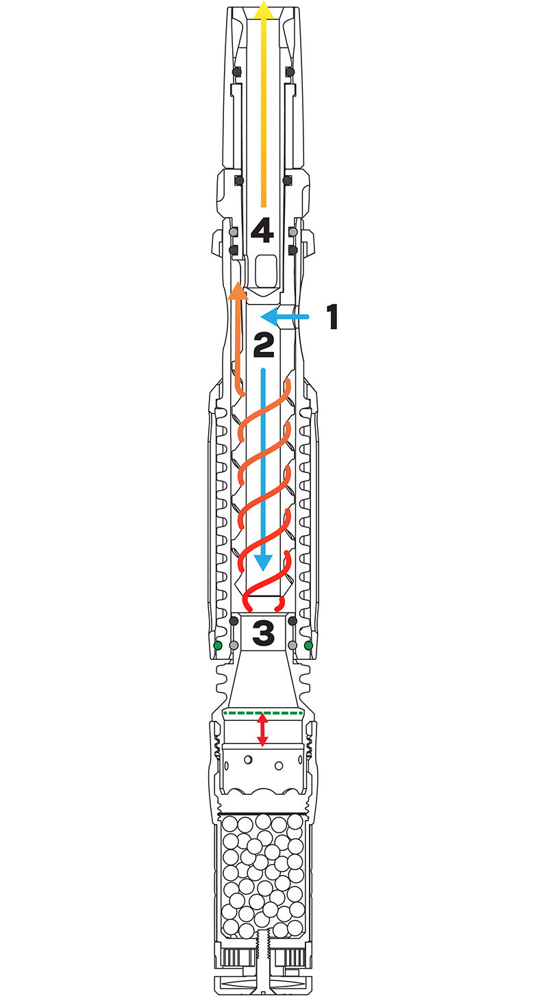
OPEN Air enters through the air hole (1) and flows through the center of the cooling unit (2) where it mixes with the vapor. It then travels over the helix (3) and finally reaches the mouthpiece (4).
BYPASS The air intake at the air hole (1) is directed straight to the mouthpiece (4) for a refreshing burst of cool air that bypasses the cooling helix (3) entirely. Meanwhile the vapor flows through the helix (3).
CLOSED By closing the air hole (1), fresh air intake is prevented which is ideal for mouth-to-lung use. This configuration promotes denser clouds while ensuring a satisfactory level of cooling through the helix (3).
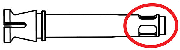
DIRECT Tube - for flavor and water pipe
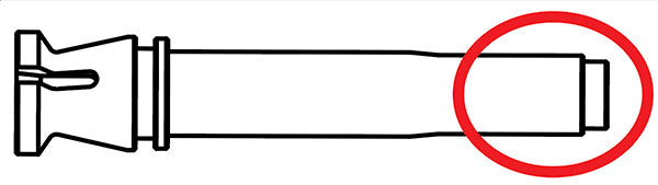
DIRECT OPEN The air intake at the air hole (1) is directed towards the mouthpiece (4), providing a refreshing burst of fresh air. Meanwhile, the vapor follows the central pathway (2) and combines with the air at the air hole (1).
DIRECT BYPASS Fresh air is drawn through the air hole (1) and routed around the helix (3), where it mixes with the vapor. The combined mixture then proceeds through the center (2) of the device and the mouthpiece (4).
DIRECT CLOSED The air hole is closed (1) to create a warm and flavorful vapor experience, providing a direct vapor path through the center (2) and mouthpeiece (4). This setup is ideal for mouth-to-lung and waterpiece use.
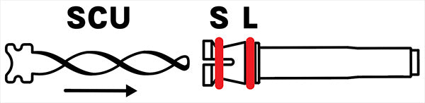
Secondary Cooling Unit (SCU)
To install the SCU for additional cooling, remove the o-ring from the spinning position (S), push the SCU into the tube, then replace the o-ring to hold it in place. If you would like to install the SCU and lock the spinning mouthpiece at the same time, use a second small o-ring (5x1mm) in the locking position (L).
Airflow Tube options
HELIX Tube - for cooling
OPEN Air enters through the air hole (1) and flows through the center of the cooling unit (2) where it mixes with the vapor. It then travels over the helix (3) and finally reaches the mouthpiece (4).
BYPASS The air intake at the air hole (1) is directed straight to the mouthpiece (4) for a refreshing burst of cool air that bypasses the cooling helix (3) entirely. Meanwhile the vapor flows through the helix (3).
CLOSED By closing the air hole (1), fresh air intake is prevented which is ideal for mouth-to-lung use. This configuration promotes denser clouds while ensuring a satisfactory level of cooling through the helix (3).
DIRECT Tube - for flavor and water pipe
DIRECT OPEN The air intake at the air hole (1) is directed towards the mouthpiece (4), providing a refreshing burst of fresh air. Meanwhile, the vapor follows the central pathway (2) and combines with the air at the air hole (1).
DIRECT BYPASS Fresh air is drawn through the air hole (1) and routed around the helix (3), where it mixes with the vapor. The combined mixture then proceeds through the center (2) of the device and the mouthpiece (4).
DIRECT CLOSED The air hole is closed (1) to create a warm and flavorful vapor experience, providing a direct vapor path through the center (2) and mouthpeiece (4). This setup is ideal for mouth-to-lung and waterpiece use.
Secondary Cooling Unit (SCU)
To install the SCU for additional cooling, remove the o-ring from the spinning position (S), push the SCU into the tube, then replace the o-ring to hold it in place. If you would like to install the SCU and lock the spinning mouthpiece at the same time, use a second small o-ring (5x1mm) in the locking position (L).
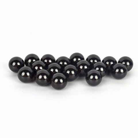
Ball options
Lower fill-weight balls heat up faster → quicker, punchier hit
The fill weights listed are approximate, actual ball sizes can vary slightly.
V1 adapter: +50 °C | V2 (plastic) adapter: –20 °C
| Ball Material | Fill Weight | YLL 3.0 Settings |
Wand Temp |
|---|---|---|---|
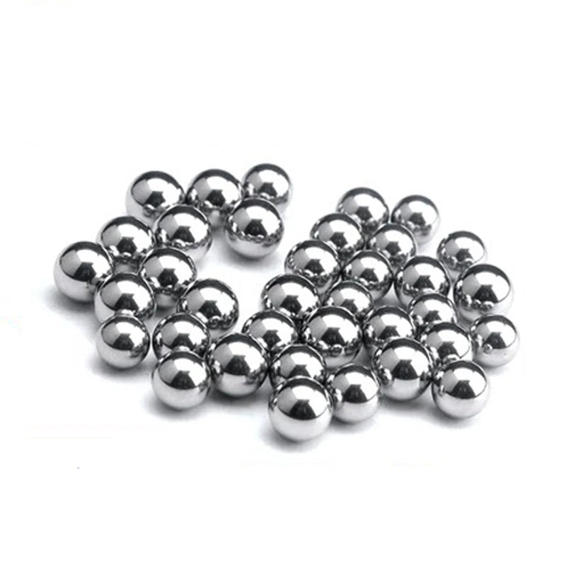
| Stainless Steel | 4.6 g | 60 W → 49–54 s 80 W → 38–43 s 100 W → 29–32 s |
320 °C / 600 °F |
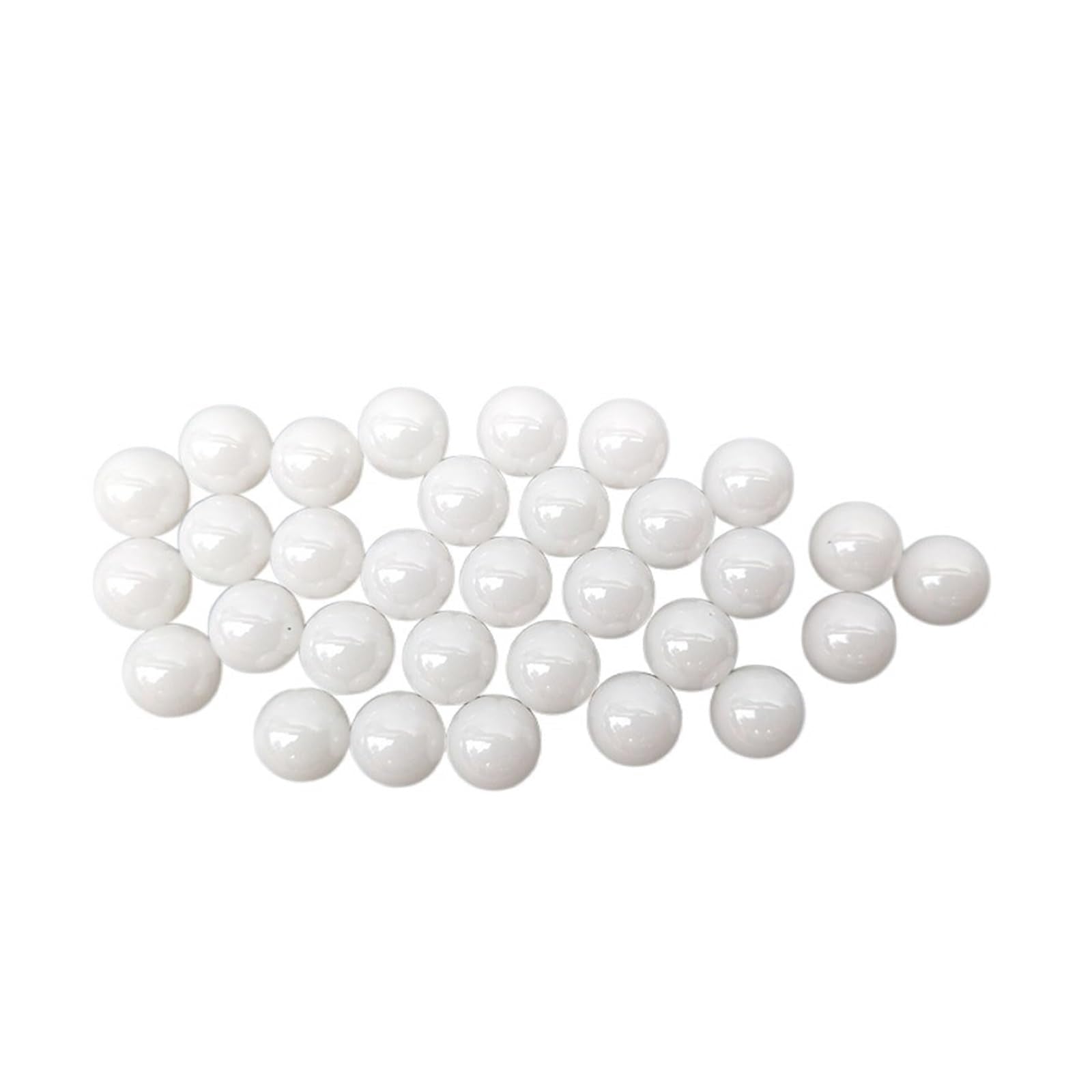
| Zirconia (Default) | 3.5 g | 60 W → 45–50 s 80 W → 35–40 s 100 W → 27–30 s |
280 °C / 525 °F |
| Ruby | 2.2 g | 60 W → 45–50 s 80 W → 35–40 s 100 W → 27–30 s |
280 °C / 525 °F |
| Silicon Carbide | 1.8 g | 60 W → 40–45 s 80 W → 31–36 s 100 W → 24–27 s |
260 °C / 490 °F |
| Borosilicate Glass | 1.3 g | 60 W → 39–43 s 80 W → 30–35 s 100 W → 23–26 s |
250 °C / 480 °F |
| Quartz Glass | 1.3 g | 60 W → 39–43 s 80 W → 30–35 s 100 W → 23–26 s |
250 °C / 480 °F |
| Ti Heater Core (V2) | 3.0 g | 60 W → 42–57 s 80 W → 33–38 s 100 W → 25–28 s |
270 °C / 510 °F |


Adjustable bowl size
Using the Reload's Debowler tool or the Airflow tube you can adjust the bowl size between 0.5cc -0.8cc ( approx. 0.075g - 0.15g )
Locking the mouthpiece
To remove the mouthpiece easily, rotate the inner tube while pulling it out, then move the o-ring to the locking position. To move the o-ring from the locking position, pinch it from both sides until it bulges, then push it to the spinning position.
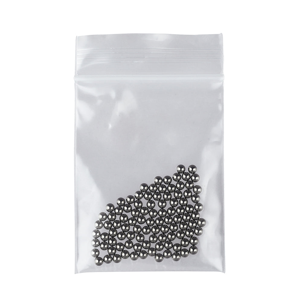
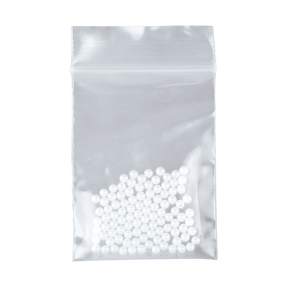
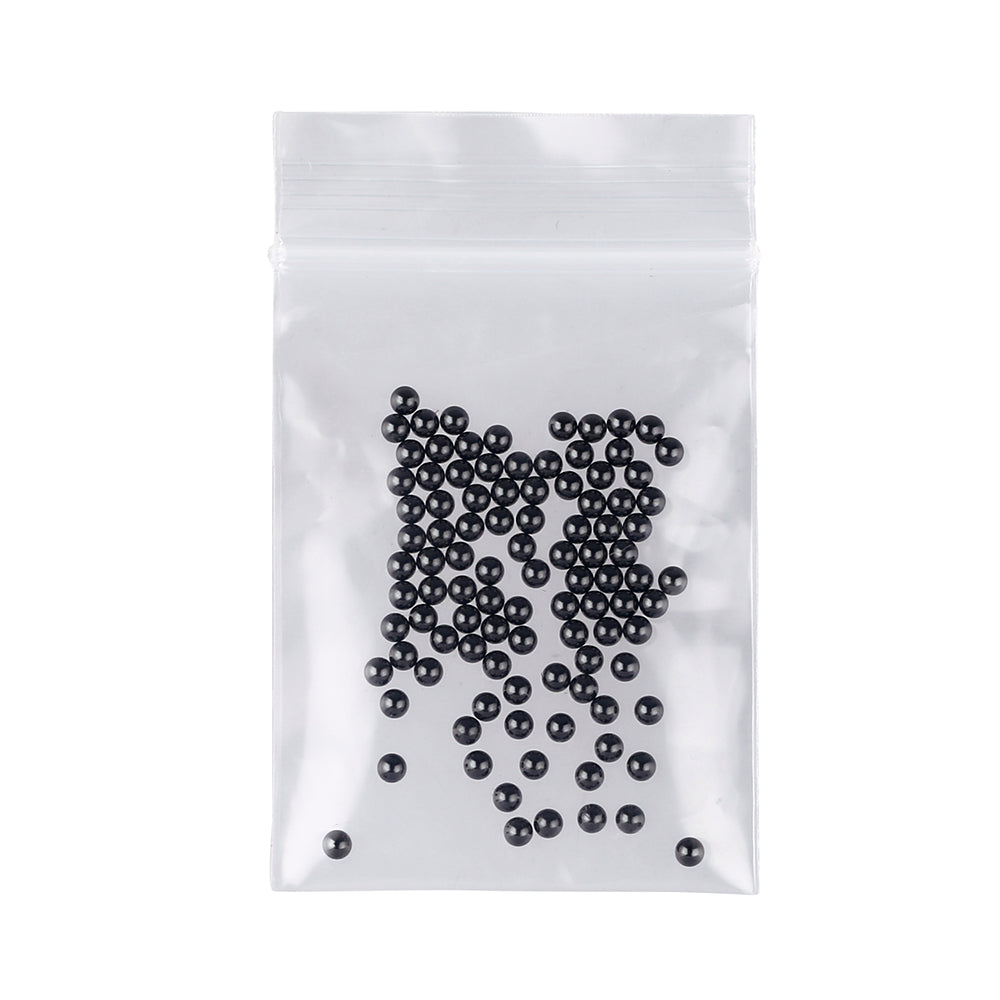
Replacing the balls
Fill the chamber with balls until they are just below the bottom of the screen threading (around 80x2.5mm or 43x3mm). Ensure the screen is flat, then center it over the thread. Apply light pressure in the middle and screw it in slowly until it reaches the end of the thread. Before fully tightening, ensure the balls can still move slightly and aren’t compressed. Keep pressing the screen’s center while tightening to prevent bulging, which would limit proper tightening.
Bowl locking tabs
Rotate the Bowl on the Radiator Sleeve so that the locking tabs align with the slots on the stem. This will provide a better grip when opening the bowl.
Installing the Heat shield
Align the notch on the outer sleeve with the line above the air port, and push the shield over the O-ring as far as possible. Ensure that the O-ring is not completely dry after cleaning; you can simply wipe your finger across it. Otherwise, it will be difficult to push into place.
Flattening the ball retaining screen
Always flatten the screen before installing. If the screen is bent, you might not be able to tighten it properly, and it could come loose within the cap.
Cleaning
Deep Cleaning (Recommended after every 100 bowls and when new)
Soak the assembled device, excluding the cap and wood sleeve, in 99% isopropyl alcohol for at least 30 minutes using a zip-lock bag, shaking it periodically to ensure a thorough clean. Drain the solution, rinse all parts in the bag with warm water, then soak again in IPA and shake for another minute to remove any leftover residue. Rinse thoroughly under hot water. Dry all parts completely before reassembling. The cap, including the indicators and balls, can be submerged in cleaning solutions; however, it must be dried as soon as possible by shaking out the remaining liquid and heating the cap once with an empty bowl. We recommend wiping it out with a Q-tip and performing periodic ball cleanings.
Quick Cleaning (Recommended after every 30 bowls)
For a quick clean, spray IPA onto the cooling spiral while holding a paper towel under it, then ‘twist off’ the spiral a couple of times. Use a Q-tip soaked in IPA to clean the inside of the sleeve and the bowl screen from below.
Wood Sleeve
Do not soak the wood sleeve in a cleaning agent. Clean only the inner metal liner with a Q-tip or pipe cleaner. Regularly apply a small amount of wax to the wood.
(Recommended after every 300 bowls)
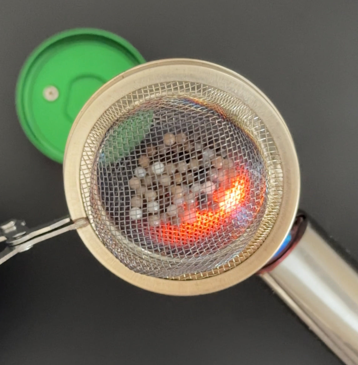
Ball cleaning
Periodically, you might want to deep clean the balls within the Cap. First, remove them and place the balls into a mesh tea strainer. Heat them repeatedly with a medium or large torch until they are clean. Be careful with the glass balls; don't heat them to extreme temperatures. Prepare a safe place for the tea strainer with the balls to cool down, which can take a few minutes.
Alternatively, you can use concentrated liquid sugar soap in a small shot glass or plastic tube. Let it sit overnight, and then shake the balls around until they are clean.
Disassembly and assembly of the indicators
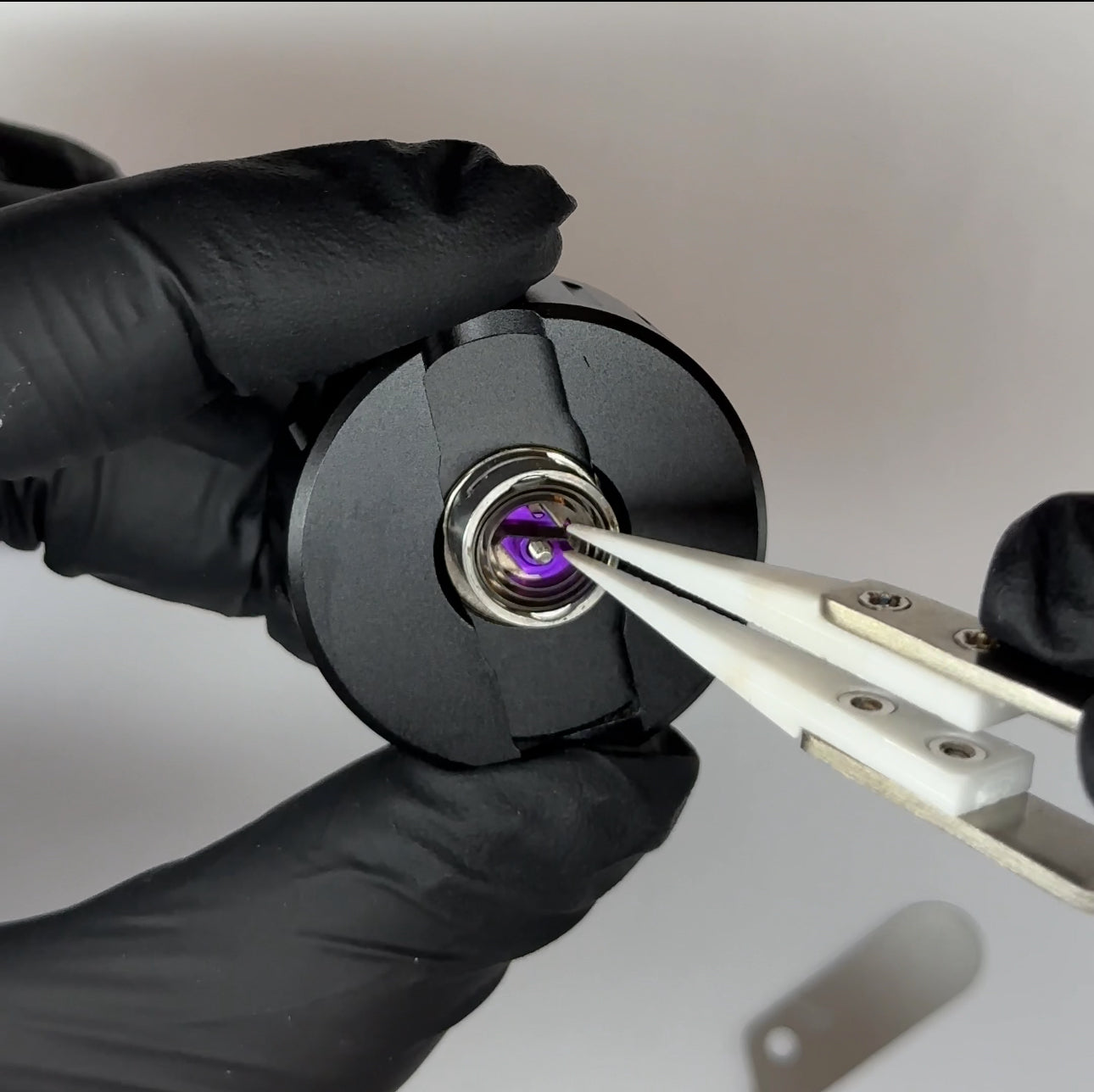
Disassembly
Please only attempt this with a clear head and a fine-point tweezer. Never try to pull the spring too much while removing it; it can bend and might not work anymore.
- Loosen the screw on the bottom of the cap by 1mm.
- Place the cap on a magnet and screw down the indicator housing.
- Grab the middle of the visual indicator spring and pull it up until it’s out of the housing.
- Push the leg through the small hole on the side of the housing to remove the spring.
- Remove the screw.
- Remove the pointer (purple part) by rotating it to the beveled section on the inner wall of the housing and lifting the other side. Make sure to rotate it to the correct position; it won’t come out otherwise.
- Flip the housing, and the click discs will fall out.
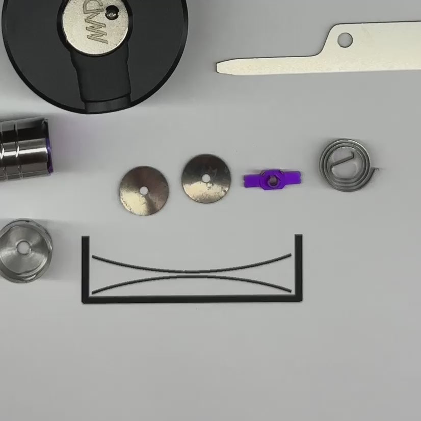
Assembly
Never force the spring too much; it can bend and might not work anymore.
- Place both click discs into the housing in the direction shown in the video.
- Install the pointer by pushing it into the side opening at the beveled section on the inner wall. The two small posts on the pointer must face in the direction of the small hole on the side of the housing, this is very important.
- Place the screw onto a magnet and push it into the housing, centering the pointer.
- Move the pointer to the starting position.
- Rotate the housing so that the small hole on the side is facing away from you.
- (a) Grab the spring in the same direction as shown in the video (again, the direction is very important) and wind it up with the tweezers. Pinch it with your fingers so it won’t unwind, then move the tweezers to the outer end of the spring to hold it together.
(b) Alternatively, you can hold the spring with your fingers, push the little leg into the hole on the side wall from a slight angle, and then push the spring into the housing. - Insert the outer end of the spring with into the hole on the side wall, then lift and rotate the center to be in between the screw and posts.
- Screw the cap back onto the indicator housing, rotate it into place, and tighten the screw.
Specification
122mm x 14mm / 4.8in x 0.55in
36g / 1.25oz
Two click discs and a visual indicator
Titanium, Stainless Steel (indicator housing, outer induction cap layer, screens) POM mouthpiece bearing, FKM (IPA safe) o-rings, Zirconia balls.
8mm Stem and Bowl connection, compatible with various DV accessories